
.svg)

Precise 3D CAD models for your building design: from point cloud to BIM model
Lumoview offers 3D models in various levels of detail, tailored to every purpose and area of application. This means that architecture and engineering firms, energy consultants and renovation planners, as well as property, asset management and BIM teams, receive exactly the information they need. No more, no less.
We provide you with:
1. Simplified 3D CAD model (simulation model): based on simplified standard elements; suitable for energy simulations and facility management, for example.
2. Architectural 3D CAD model (architectural model): including precise dimensions and room designations, displayed as built, suitable for architectural planning and scan-to-BIM.
3. Customised 3D CAD model: Precisely controlled model exactly according to your specifications, suitable for the highest individual demands.
Benefits of 3D CAD modelling with Lumoview
Whether you need a simplified existing model or a highly detailed custom model, we deliver exactly the 3D CAD model you need for your project phase.
Reliable basis for energy simulations
A valid 3D CAD model is absolutely essential for any energy simulation or calculation. Whether for shading analyses, thermal bridge evaluation or detailed quantity determination: our data is structured geometrically so that it can be processed directly in common BIM or energy calculation software. Such an energy model provides reliable data for your renovation concepts.
Maximum planning reliability through to accurate as-built data
Our digital building models help avoid surprises during construction by making complex conditions visible—from complicated roof geometries to critical utility routes. This transparency supports design comparisons and renovation concepts while providing the necessary data to identify risks early and create reliable cost estimates.
Compatible: Seamless BIM workflows through scan-to-BIM
Modern planning, CAD, and BIM tools increasingly rely on 3D as the standard format. Our Scan-to-BIM workflow enables smooth integration into modern software ecosystems and automated Building Information Modeling processes. This ensures that your as-built data remains future-proof and interoperable across systems.
Exactly the level of detail your project needs
From simplified as-built models to highly detailed architectural models, Lumoview provides the exact level of detail required for each project stage—no more and no less. Choose a simplified model for quick simulations or a detailed architectural model for precise planning. We deliver the right model for your needs.
The right 3D CAD model for every use case
We measure your building room by room with our LumoScanner and, optionally, also capture the building envelope using drone flight. We then create a
3D CAD model that exactly meets your needs. Our digital model building transforms the scan data into an accurate 3D as-built model, which is available in various levels of detail (LOD) and can be flexibly adapted to your specific requirements – ideal for complex planning and detailed building analyses.
Levels of detail at a glance
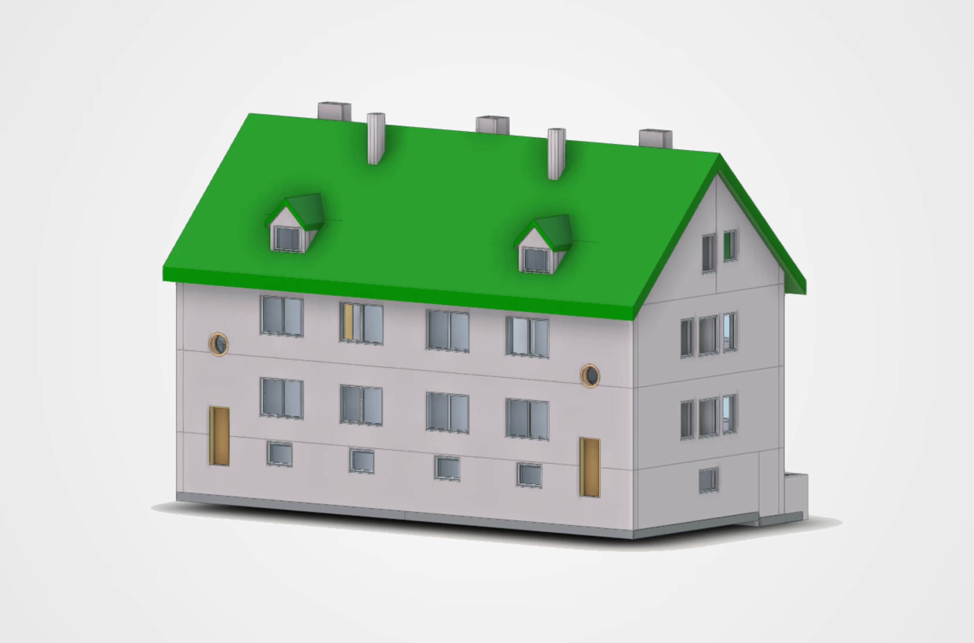
Level 1: Simplified 3D simulation model
The simplified 3D CAD model provides basic building data with standardised elements and some simplifications. It forms an efficient and precise basis for energy simulations, energy consulting, facility management and initial renovation planning work, such as cost calculations. We focus on the space-defining geometry and deliberately avoid unnecessary complexity in order to maximise performance in your simulation software.
.avif)
The 3D simulation model includes the following services:
General & geometry:
The model is created as a closed overall building (not separated by address). It contains a simplified geometry of the space-defining elements: floor, ceiling, roof, walls, openings and stairs. The elements are represented as solids.
Walls:
Interior and exterior walls are differentiated (exterior wall thickness is measured). Shafts are represented as closed wall surfaces, exterior walls Mitred corners. The walls are separated by storeys (floor slab to inside wall). Glass partitions in the interior are modelled in glass, but without subdivisions/frames.
Ceiling & floor:
A standard floor slab is modelled (floor thickness with large tolerances). Openings for stairs and height differences in the floor slab are included. Floor slabs extend to the outer edge of the wall.
Windows & doors:
Standardised, simplified elements are used with information about the type of opening for doors. Windows are divided simply (up to Three-part, also shown as a three-part window). Glazed exterior doors are differentiated (floor-to-ceiling windows available on request). Interior and exterior doors are differentiated. Skylights are simplified to rectangles. Dimensions are prioritised according to manual, precise measurement, 3D laser scanning with the LumoScanner or photogrammetric estimation.
Stairs & balcony:
Stairs are simplified, the number and dimensions of the risers are not exact, but are constructed generically. Railings and balustrades are represented as generic constructions, solid parapets as railings). Intermediate landings are included. Balcony slabs are simplified and modelled as extensions of the floor slab.
Roof:
The roof geometry is simplified. Roof overhang is estimated based on photos (if no other data is available). Dormers and Standard roof windows (simplified, single-piece) are included. The roof thickness is estimated. The knee wall is simplified as a vertical wall.
Context & space:
The model zero level (Z=0.00) refers to the ground floor (OKFF) . The building orientation is indicated by a north arrow. Room numbers and names are based on the Lumo standard.
The following services are not included:
Components:
No joists, beams, chimneys, niches, WC pre-walls, heating niches and radiators (no building services).
Material & structure:
No material allocation (no information about surfaces). No wall, floor or roof structure (no layer structure). No material differentiation between solid and drywall construction in the interior.
Ceiling:
No suspended ceilings (room height is based on the highest room). Details of openings: No information about construction, material or design. No precise details about horizontal or vertical divisions. No horizontal window divisions. No information about how deep the window is set into the wall.
Roof details:
No rafters. No precise external roof geometry with drone flight. Surroundings: No modelling of the terrain or outdoor facilities.
Room data:
No differentiation between heated and unheated rooms.
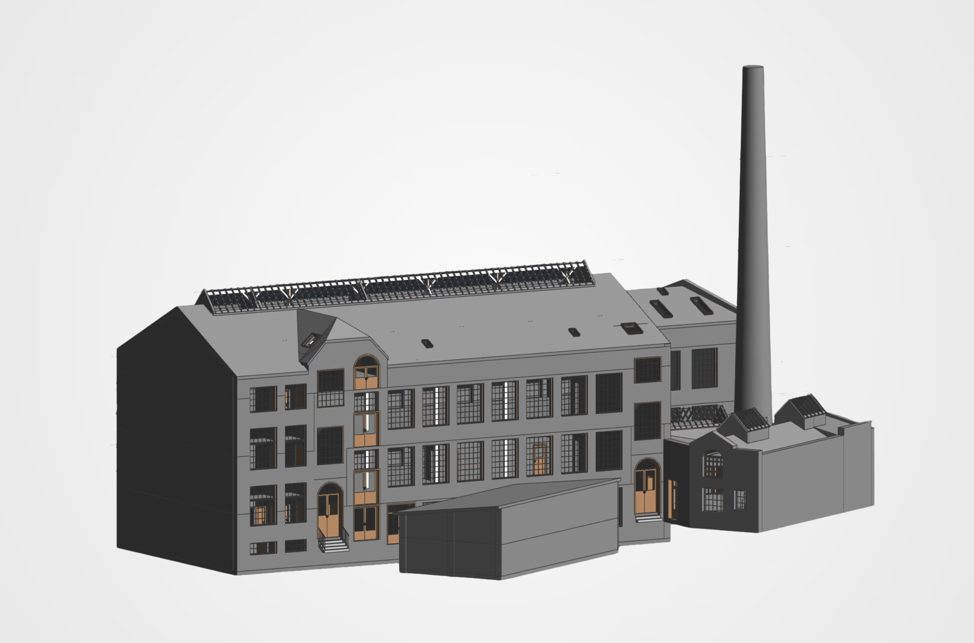
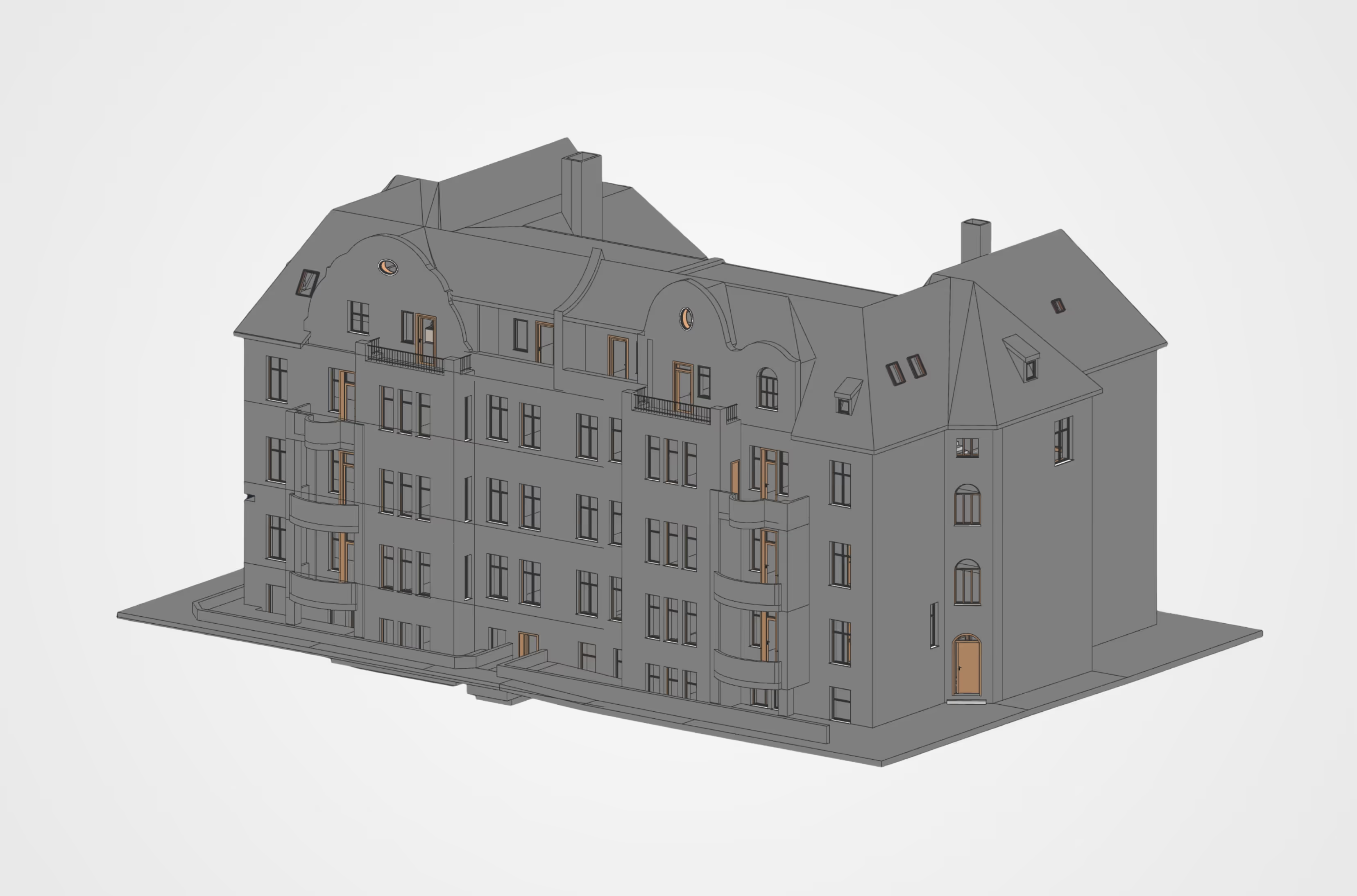
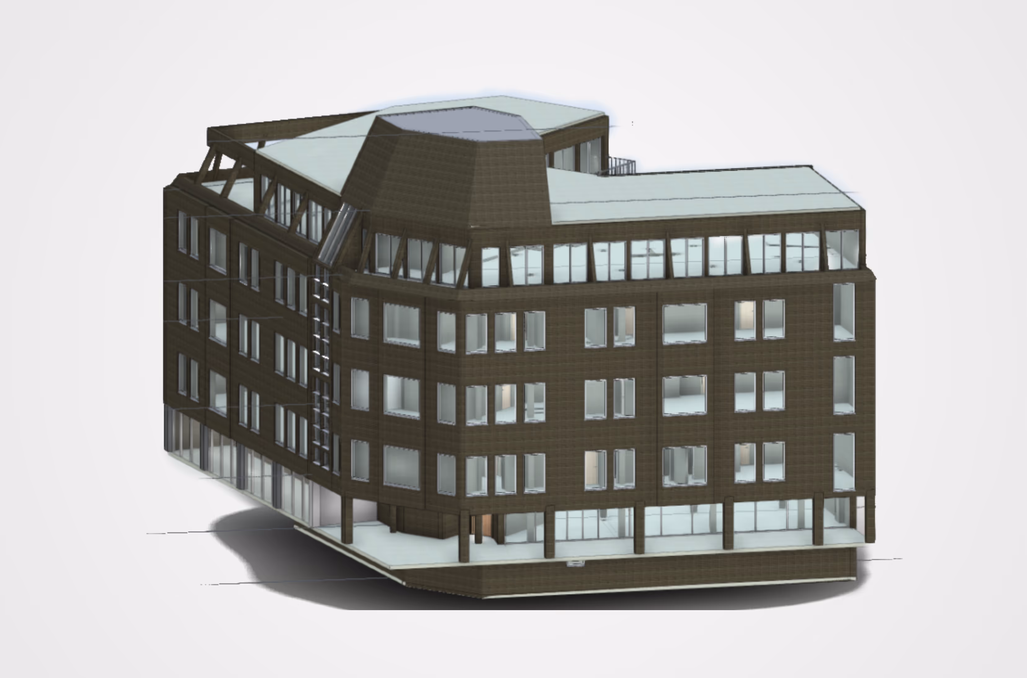
Level 2: Detailed architectural 3D model
The detailed architectural 3D model contains exact dimensions and room designations. Components such as doors and windows are modelled in their as-built state. You receive a detailed interior and exterior model with doors, windows, stairwells, roof structures and other possible elements. This makes it ideal for architectural planning and scan-to-BIM workflows.
The architectural model includes the following services:
General & geometry:
The model is created as a closed overall building (not separated by address). It includes all elements visible in the room: floor, ceiling, roof, walls, openings, stairs, joists, beams, chimney and niches. The elements are represented as solids.
Walls:
A distinction is made between interior and exterior walls; the thickness of the exterior walls is measured. Shafts are represented as closed wall surfaces, exterior walls at corners are mitred. The walls are separated by storeys. Exterior walls are represented as continuous facades from OKFB to OKFB, with the floor slab extending to the inside of the wall. Glass partitions in the interior are modelled using glass with subdivisions/frames (curtain wall elements). WC pre-walls and heating niches are included.
Ceiling & floor:
A standard floor slab is modelled (floor thickness with large tolerances). Openings for stairs and height differences in the floor slab are included. Floor slabs extend to the inner edge of the wall. Suspended ceilings are included. The shell construction is based on the highest room; individual rooms with different heights are given a suspended ceiling.
Windows & doors:
Standardised, simplified elements are used with information about the type of opening. The elements are precisely subdivided, with precise information about the horizontal or vertical subdivision. Glazed exterior doors are differentiated and, on request, can also be designed as floor-to-ceiling windows. Interior and exterior doors are differentiated. Skylights are simplified, but with realistic geometry. Dimensioning is prioritised according to manual measurement, 3D scanning withthe LumoScanner or photogrammetric estimation. Information on the reveal depth of the windows is simplified.
Stairs & balconies:
Stairs are simplified, with the number and dimensions of the steps are as accurate as possible. In the construction, the material is differentiated according to wood, concrete or steel. Railings and balustrades are simplified as generic constructions. Intermediate landings are included. The balcony slab thickness is determined by measurement. If no information is available, it is simplified as an extension of the floor slab.
Roof: Main rafters are depicted without diagonal or complex geometries , and the roof overhang is based on 3D scans and photogrammetric images. Dormers and standard roof windows are included. The roof thickness is estimated and, where possible, determined on site. The knee wall is included. A precise external roof geometry with drone flight is included (using drone images).
Context & space: The model zero level refers to the terrain, i.e. it is aligned with the main entrance of the building. The ground floor is at ± X.XXm. building orientation is indicated by a north arrow. Room numbers and names are based on the Lumo standard.
The following services are not included:
Components:
No building services, design details (decorations), no construction details and radiators.
Materials & construction:
No material allocation (no information about surfaces). No wall, floor or roof construction (no layer structure). No differentiation between solid and drywall construction in the interior.
Details of openings:
No information about construction, materials or design.
Surroundings:
No modelling of the terrain. Room data: No differentiation between heated and unheated rooms.
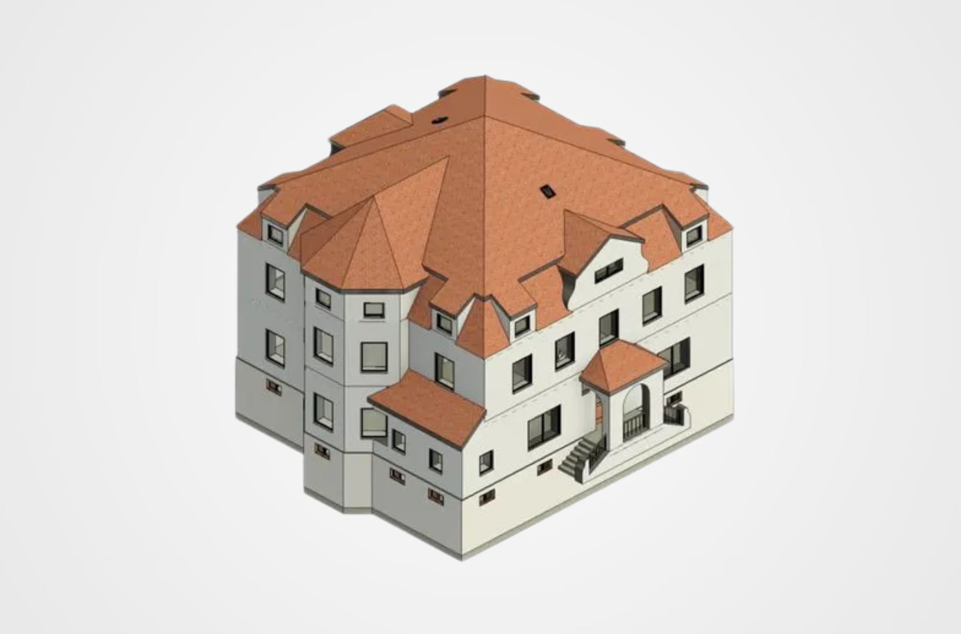
Level 3: Customised 3D CAD model
.avif)
The customised model includes the following services:
- General & requirements:
The model is a detailed representation based on customer specific requirements. It offers a comprehensive and detailed In-depth information covering all aspects with high precision. It is indispensable for detailed planning, specialised applications and the most demanding requirements.
- Scope:
The scope of services includes complete interior and exterior modelling. This explicitly includes doors, windows, stairwells and the roof structure.
- Details & fittings:
The model offers extensive details for doors, windows, ceilings and walls. Textures, detailed furnishings and simple materials are included on request.
- Technology & extensions:
The building services components can be displayed according to your requirements. Also integrated are detailed images via the LumoApp and the PV add-on (for photovoltaic planning).
- Formats:
We provide the model in common formats such as RVT, IFC and DWG, as well as exports to ERP, CAFM and BIM (other formats, such as HottCAD, available on upon request).

Use cases: Who is the 3D CAD model suitable for?
Thanks to its high degree of customisation, Lumoview 3D CAD modelling is suitable for numerous applications, particularly in the fields of energy consulting and energy-efficient renovation, as well as digital building inventories and facility management.
Specialist planners and architectural firms
receive precise as-built models for their design and implementation planning. Our architectural models (Level 2) integrate seamlessly into your BIM workflows and save you time-consuming on-site measurements.
Engineering firms
use both simplified and detailed models for static analyses or building physics simulations. Depending on the application, whether structural design, building services or complex specialist planning, you can select exactly the level of detail your calculation requires.
Energy consultants and renovation planners
require geometrically valid models as a basis for any energy assessments and renovation planning. Our simplified models without unnecessary details (Level 1) are optimised for this purpose.
Property and portfolio managers
receive structured CAD models that serve as a reliable basis for documentation, space management and building analysis. This allows you to organise your data.
Construction companies and project managers
need precise 3D data sets as a reliable basis for tenders, quantity surveys and smooth process planning and coordination on the construction site.
PropTech/BIM teams
can integrate our 3D models as digital twins directly into their digital platforms or inventory digitisation systems. We provide the compatible database for your digital ecosystems.
Frequently asked questions about our 3D CAD data
As standard, we supply open formats such as IFC (Industry Foundation Classes), which are compatible with most CAD and BIM programmes. Native formats such as RVT (Autodesk Revit) or DWG are also possible. Please contact us for special requirements (e.g. HottCAD).
- Level 1 is a simplified model, ideal for energy simulations. Walls are represented as idealised surfaces without thickness, windows and doors are simplified openings.
- Level 2 (architecture) is a detailed architectural model for planning purposes. Here, walls have real thicknesses and multiple layers, windows and doors have frames and sashes, and the roof truss is represented including rafters.
- Level 3 is a customised model that includes all the requirements you need.
The standard Levels 1 and 2 do not include any technical building equipment such as heating, ventilation or electrical systems. If you require these elements, we offer them as an optional service in Level 3 (customised).
Our models are based on precise laser scans (LumoScanner). Level 1 focuses on simplified geometry. Level 2 precisely dimensions components such as windows and doors (priority: manual measurement > scan > photo). Level 3 provides detailed modelling according to your specific requirements.
Yes. The Lumoview Level 1 (Simplified) model is specially designed to have a "lean" 3D geometry (only space-defining elements). This facilitates import and calculation in common simulation software.
In the standard packages (Levels 1 & 2), modelling ends at the building envelope, i.e. the terrain or outdoor facilities are not included. However, we can model these for you in Level 3 (Customised) on request.
In Level 1, a simplified roof geometry (including dormers) is created.
In Level 2, main rafters are shown, but no diagonal or complex geometries. Precise external roof geometry is possible with drone flight.
For special and specific requirements, we create a detailed model in Level 3 based on your specific requirements.
The delivery time depends on the desired level of detail, the complexity of the building and the size of the building. We would be happy to provide you with a precise estimate without obligation.
2D plans only show sections, but not connections. A 3D model makes spatial situations visible and is essential for energy simulations, shading analyses and BIM processes.
That depends on your intended use:
- Level 1 (Simplified) is the right level of detail for energy simulations and facility management. It offers simplified geometry (only space-defining elements) and idealised 2D surfaces without wall thickness.
- Level 2 (Architecture) is the right level of detail for architectural planning and scan-to-BIM. It includes all elements visible in the room, multi-layer walls with real thicknesses, and a precise subdivision of windows and doors.
- Level 3 (Customised) is suitable for the most demanding requirements. It is a detailed model based on your specific requirements.
The cost depends on the level of detail you choose. Feel free to contact us and tell us what you need.

Unlock efficient BIM workflows today!
Tailored 3D CAD and BIM models for reliable project planning.en